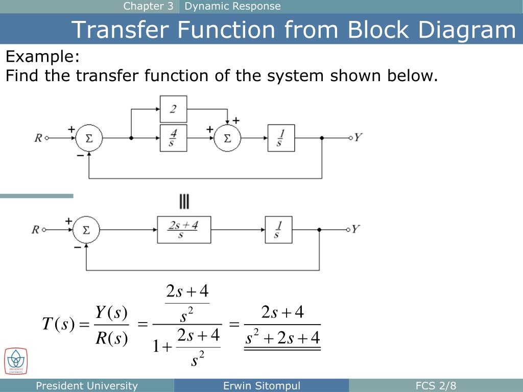
Block diagram function transfer find below system ppt powerpoint presentation chapter response dynamic shown example
Table of Contents
Table of Contents
If you’re an engineering student or professional, you may have encountered the need to draw block diagrams from transfer functions. While this task may seem daunting, it is an essential skill that can be easily learned with some simple guidelines.
The process of drawing block diagrams from transfer functions can be challenging for many students and professionals, particularly those who are new to the field. This can be due to a lack of understanding of the concepts involved or a lack of familiarity with the necessary tools and techniques.
The first step in drawing block diagrams from transfer functions is to understand the concept of a transfer function. A transfer function is essentially a mathematical representation of the relationship between an input signal and an output signal in a system. It is typically represented as a ratio of polynomials in terms of the Laplace variable s.
Once you have a good understanding of transfer functions, you can begin the process of drawing block diagrams. The first step is to identify the individual components of the system and their corresponding transfer functions. These components can then be connected using block diagram manipulation rules to produce a complete block diagram representation of the system.
In summary, to draw block diagrams from transfer functions, you need to understand the concept of transfer functions, identify the individual components of the system, and then use block diagram manipulation rules to connect these components.
How to draw block diagrams from transfer functions - Step by Step Guide
When I was first learning how to draw block diagrams from transfer functions, I struggled with the process. However, once I understood the basic steps involved, the task became much easier. Here is a step-by-step guide on how to draw block diagrams from transfer functions:
### Step 1: Break down the system into individual components
The first step in drawing block diagrams from transfer functions is to identify the individual components of the system and their corresponding transfer functions. For example, consider the following system:
 The transfer function for this system can be expressed as:
Y(S)/U(S) = G1(S) * G2(S) / [1 + G2(S) * G3(S)]Here, the individual components of the system are G1(S), G2(S), and G3(S).
Step 2: Draw individual blocks for each component
The next step is to draw individual blocks for each component. These blocks should represent the transfer function for each component. For example, consider the individual blocks for the components in the example system:

The final step is to connect the individual blocks to form the complete block diagram for the system. This can be done using block diagram manipulation rules. For example, consider the block diagram for the example system:
 Why is it important to learn how to draw block diagrams from transfer functions?
Knowing how to draw block diagrams from transfer functions is essential for engineers and engineering students. Block diagrams are a powerful tool for modeling complex systems and understanding the behavior of these systems. By converting transfer functions into block diagrams, engineers can gain a better understanding of the interactions between different components of a system and identify potential problems or areas for improvement.
How to simplify block diagrams?
One of the challenges in drawing block diagrams from transfer functions is dealing with complex systems that may be difficult to visualize. In these cases, it is often useful to simplify the block diagram to make it more manageable. Block diagram reduction techniques can be used to simplify complex block diagrams by removing unnecessary blocks, merging blocks, or rearranging the order of blocks.
What is the difference between a signal flow graph and a block diagram?
A signal flow graph is another graphical representation of a system that is similar to a block diagram. However, a signal flow graph focuses on the flow of signals through a system, while a block diagram focuses on the components of a system and their interactions. Signal flow graphs are often used in control systems engineering and can be a useful tool for analyzing system behavior.
Conclusion of how to draw block diagrams from transfer functions
Drawing block diagrams from transfer functions is an essential skill for engineers and engineering students. By understanding the basic steps involved and using block diagram manipulation rules, you can easily convert transfer functions into block diagrams and gain a better understanding of complex systems.
Question and Answer
1. Why are block diagrams useful in engineering?
Block diagrams are useful in engineering because they provide a visual representation of complex systems and their components. This can help engineers to better understand the interactions between different parts of a system and detect potential problems or areas for improvement.
2. How do you simplify block diagrams?
There are several techniques that can be used to simplify block diagrams, including removing unnecessary blocks, merging blocks, or rearranging the order of blocks. Block diagram reduction rules can also be used to simplify complex systems.
3. What is a transfer function?
A transfer function is a mathematical representation of the relationship between an input signal and an output signal in a system. It is typically represented as a ratio of polynomials in terms of the Laplace variable s.
4. What is the difference between a signal flow graph and a block diagram?
A signal flow graph is another graphical representation of a system that focuses on the flow of signals through a system, while a block diagram focuses on the components of a system and their interactions.
Gallery
PPT - The Block Diagram PowerPoint Presentation, Free Download - ID:5668999
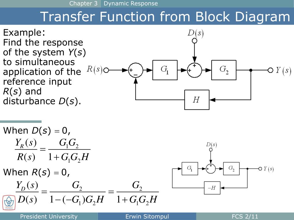
Photo Credit by: bing.com / block diagram function transfer find ppt powerpoint presentation response chapter dynamic system
42 Block Diagram Transfer Function - Diagram For You
Photo Credit by: bing.com /
PPT - The Block Diagram PowerPoint Presentation, Free Download - ID:5668999

Photo Credit by: bing.com / block diagram function transfer find below system ppt powerpoint presentation chapter response dynamic shown example
Determine The Transfer Function Of The Above Block | Chegg.com
Photo Credit by: bing.com / determine transfer function block above
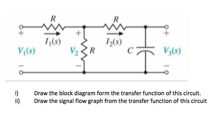
Solved Draw The Block Diagram Form The Transfer Function Of | Chegg.com

Photo Credit by: bing.com / transfer block diagram function draw solved form transcribed problem text been show

