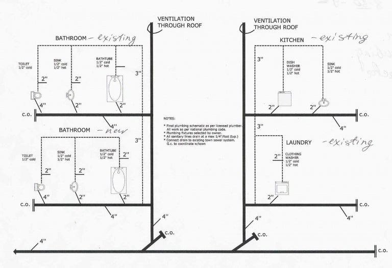
Permit riser
Table of Contents
Table of Contents
In the architecture and construction industry, drawing a plumbing riser diagram is a crucial part of any building plan. This detailed plan provides insight into the plumbing system, showing where each fixture connects to pipes and how the system runs throughout the building. Whether you’re an architect, engineer, or DIY homeowner, learning how to draw a plumbing riser diagram is essential to any plumbing project.
When it comes to drawing a plumbing riser diagram, there are many pain points that one can encounter. Some common challenges include understanding the various symbols and codes, figuring out how to map out the entire system, and determining the best placement for each fixture. Additionally, because a plumbing riser diagram is such an integral part of any building plan, mistakes can lead to costly setbacks and delays.
Fortunately, learning how to draw a plumbing riser diagram is not as difficult as it may seem. The first step is to gather all necessary information, including the location and size of each fixture, pipe material, and fixture units. With the appropriate information, you can then start mapping out the entire system, including the main drain, vent pipes, and water supply lines.
To create a plumbing riser diagram, start with the vertical pipe that runs through the building and connects all of the horizontal pipes. Draw a line representing this pipe and label it as the main stack. Next, indicate each floor of the building and draw horizontal lines to represent pipes that connect fixtures on each floor. Be sure to label each line accordingly by listing the fixture unit and its corresponding pipe size.
Drawing a Plumbing Riser Diagram – Tips and Tricks
When I was in my first year of architecture school, my professor recommended breaking the process down into smaller sections, starting with one floor at a time. This made it much easier to focus on the details and ensure that everything was accurate before moving on to the next floor. I also found it helpful to use software programs such as AutoCAD or Revit, which have specific features that make drawing a plumbing riser diagram much more efficient.
Common Mistakes When Drawing a Plumbing Riser Diagram
One of the most common mistakes is forgetting to include all necessary information, such as pipe size and fixture units. Another mistake is failing to accurately label each line, which can make it difficult to follow the flow of the plumbing system. Finally, not double-checking all of the measurements and details can lead to incorrect placement of fixtures, pipes, and other essential components.
Understanding Plumbing Riser Diagram Symbols and Codes
Learning the various symbols and codes used in plumbing riser diagrams is essential to ensuring accuracy and efficiency. Some common symbols include inverted “Y” with a horizontal line, which represents a cleanout, and the diamond shape, which indicates a valve. Understanding these symbols and codes can save time and help prevent costly mistakes.
The Importance of Accuracy in Drawing a Plumbing Riser Diagram
When it comes to drawing a plumbing riser diagram, accuracy is key. Even small mistakes can lead to significant problems down the line, such as leaks, clogs, and uneven water pressure. Taking the time to double-check all measurements, labels, and details can save time and money in the long run.
FAQs About Drawing A Plumbing Riser Diagram
What is a Plumbing Riser Diagram?
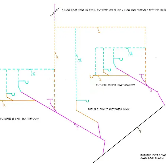
A plumbing riser diagram is a detailed plan that shows the entire plumbing system of a building. It includes information about the location and connection of each fixture, the size and material of each pipe, and the placement of vent and drain lines.
Why is a Plumbing Riser Diagram Important?
A plumbing riser diagram is an essential part of any building plan, as it provides insight into the plumbing system and helps ensure that everything is properly connected and in compliance with building codes. It is also a valuable tool for maintenance and repair, as it allows plumbers to quickly identify and locate issues.
What are Some Common Symbols Used in Plumbing Riser Diagrams?
Some common symbols used in plumbing riser diagrams include the diamond shape for valves, the inverted “Y” with a horizontal line for cleanouts, and the circle with a horizontal line for floor drains. Additionally, each fixture is represented by a specific symbol, such as a toilet or sink.
What Software Programs are Best for Drawing Plumbing Riser Diagrams?
Some of the best software programs for drawing plumbing riser diagrams include AutoCAD, Revit, and SketchUp. These programs have specific features that make it easier to create accurate and detailed diagrams, and also allow for easy editing and sharing of files.
Conclusion of How to Draw a Plumbing Riser Diagram
Drawing a plumbing riser diagram may seem daunting, but it is an essential skill for anyone involved in the construction, design, or maintenance of buildings. By following these tips and tricks, avoiding common mistakes, and understanding the symbols and codes used in plumbing riser diagrams, you can create accurate and detailed plans. With the appropriate knowledge and tools, you can ensure that your plumbing system runs smoothly and efficiently for years to come.
Gallery
Plumbing Riser Diagram Example

Photo Credit by: bing.com / riser plumbing diagram example wrong venting pump diychatroom multi drawing bathroom sanitary waste whats f7 building sewage basement storey attachments
Draw Plumbing Plans – Master Plumber Tim Carter Can Draw Your Plumbing

Photo Credit by: bing.com / permit riser
Andrew Mawby: How To Draw Plumbing Plans

Photo Credit by: bing.com /
Help With A Riser Diagram With Regard To How To Draw A Plumbing Riser

Photo Credit by: bing.com / riser plumbing venting
Plumbing Riser Diagram Symbols

Photo Credit by: bing.com / riser plumbing diagram symbols drawing diagrams building system plan drawings piping isometric create floor representation level


